

- October 14, 2026
- by Almifthaah
Best Cutting Speeds and Feed Rates for Carbide Tipped Tools
Selecting the appropriate feed rate and cutting speed is essential to get the optimum cutting result. Carbide-tipped tools can tolerate a great deal more heat and wear than high-speed steel, but that doesn’t make the settings any less critical. Being a leading Carbide Tipped Single Point Tools supplier in Dubai, Almifthaah recognizes that small variations in parameters can have a significant impact on the results in an actual shop.
This guide will give you the core formulas, useful parameters, and errors most often committed by machinists. So even if you do turning, boring or milling, the following tips will help you achieve excellent durability and accuracy.
Table of Contents
ToggleKey takeaways
- Begin with the cutting speed recommended by the manufacturer for the tool you are using.
- Find out the spindle speed based on the cutting speed formula.
- Make necessary feed rate adjustments so that the chip thickness and quality are not disturbed.
- Note the results and adjustments made for this operation to make sure that consistent conditions can be used in future jobs.
What are cutting speed and feed rate?
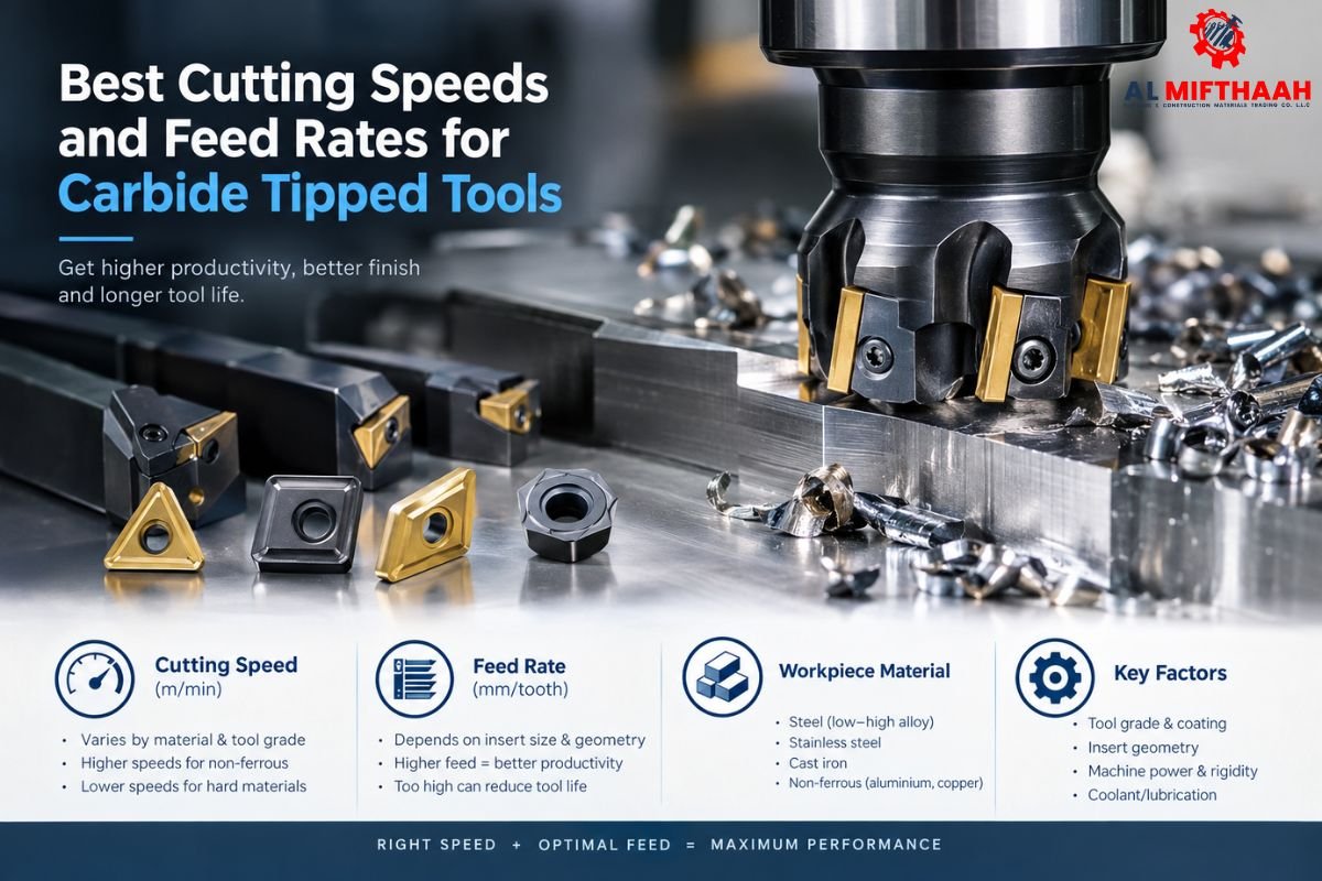
Cutting speed is the speed at which the cutting edge moves over the surface of the material being cut (m/min). Feed rate is how much the tool advances per spindle revolution and per tooth, typically expressed in millimeters. These two combine to decide chip thickness, heat per chip, and tooling life.
It is important to understand that speed and feed rate go hand in hand and cannot be optimized without one impacting the other. The quicker the edge moves through the material, the greater the heat will be concentrated at the edge. That heat is not a problem for carbide and is one of the reasons why it can operate at a much higher speed than high-speed steel. But when the speed is above the limit, the wear of the crater will increase and may lead to sudden failure at the edge of the crater.
The amount of chip thickness is controlled by feed rate, and the amount of load per cutting edge is controlled by chip thickness. Light feed produces rubbing and build-up of heat without effective removal of material. Heavy feed will cause overloading of the edge and may lead to chipping. The key to good machining is to balance these variables among themselves and against your machine’s ability.
Several factors shape the right settings for any job:
- Hardness of the material: harder materials will typically require slower speeds to accommodate the heat.
- Tool geometry: nose radius, rake angle, and coating affect how the edge engages.
- More machine rigidity: more aggressive settings will be used with a stable spindle, holder, and workpiece.
How do you calculate cutting speed?
Calculation of cutting speed Vc (m/min) = (π × D × N) / 1000. D = diameter of the part (mm). N = spindle speed (rpm). π is 3.14. For spindle speed, N = (Vc x 1000)/ (3.14 x Diameter). For using the supplied table or choose a suggested speed from the manufacturer then adjust for the machine and material.
- Turning Formula
In turning, D is the diameter of the part being turned. Suppose a bar of 50 mm is to be turned at 180 m/min. The spindle speed becomes N = (180 × 1000) / (3.1416 × 50), which works out to roughly 1,146 rpm. You can then use that as a starting point and pass a test, then look at the finish and chip colour before making changes.
- Milling Formula
D is the diameter of the cutter in milling. If spindle speed is given as 3,183 rpm, and the 12 mm 4-flute carbide end mill is used at 120 m/min, the spindle speed is approximately correct. Feed per minute is then Vf = fz × z × N, with the number of flutes z and feed per tooth fz. The table feed is approximately 637 mm/min with fz = 0.05 mm. Carbide End Mills Supplies Dubai can offer you as a reliable supplier that will be able to provide you with the best geometry for these numbers.
What are good starting speeds for common materials?
There is no definitive rule for the recommended starting speeds for different materials. Aluminium is the fastest material available, followed by stainless steel and then titanium, which needs to be run at a slower speed for thermal control. The following table provides some suggested starting ranges for carbide-tipped tools. Always double-check final values in your insert manufacturer’s catalog and fine-tune them with test cuts.
These ranges are indicative and not guaranteed. The ideal number varies depending on the condition of the machine, depth of cut, grade of the coating, and coolant. Think of the table as a starting point, rather than an endpoint.
| Material | Typical Cutting Speed (m/min) | Feed Guidance |
| Mild steel | 150–250 | Medium to high |
| Alloy steel | 100–180 | Medium |
| Stainless steel | 70–140 | Light to medium |
| Cast iron | 100–200 | Medium |
| Aluminum | 300–800 | High |
| Titanium | 40–80 | Light |
The Sandvik Coromant Knowledge Center provides comprehensive advice on machining for more in-depth information on the effect of grades and coatings on these numbers. See ISO standards for metal cutting for the standards that define shared machining terminology. After the turning deburring process, if your process requires it, look at the Carbide burr supplier or carbide end mill supplier in the Dubai range.
How does feed rate affect tool life and surface finish?
The feed rate directly affects the thickness of the chips, surface finish, and cutting force. A moderate, consistent feed typically will produce the longest tool life. Heavy feed chips the carbide tip, and light feed causes rubbing and a built-up edge. Make small changes to the feed and find the optimum balance for your system.
Surface finish is better with lower feed and lower nose radius since the ridges formed will be smaller. Theoretical roughness is a function of the square of feed over nose radius in turning. Hence, the larger the nose radius, the more moderate the feed, the smoother the part. When the setup is not “loose,” finishing passes can be done lighter and roughing passes can be done heavier.
Changes in feed also impact heat. A slightly heavier feed can also remove heat in the chip, beneficial in materials that tend to work-harden. When you are tuning, pay attention to the changing shape and sound of chips; this will help you notice problems long before they become visible on the surface. Browse the full catalogue of cutting and milling tools Dubai, and choose the perfect tools for your needs, available for roughing and finishing.
What are the best practices for carbide-tipped tools?
Some best practices are having pre-use checks of tools, setups to be rigid, coolant to be used as appropriate, and changes to be made incrementally. Carbide is best used in an environment where the machine, holder, and workpiece are stable. Your settings are also recorded, which helps greatly with achieving the same results on different production runs.
- Check the insert and holder for wear, cracks, or looseness before each job.
- Run at the manufacturer’s recommended rate and feed for the grade.
- Test run and inspect the surface finish, sound, and the chip colour.
- Try cutting speed first, followed by feed; increment by 10 percent.
- Document final settings and tool life for future jobs to ensure the use of proven data.
Prior to the next run, check our cutting and milling tools Dubai catalog for grades that are appropriate to your material. It’s also important to have consistent sourcing. Almifthaah is also a Saif Precision tools supplier in UAE to ensure uniformity of inserts and holders throughout the job.
What mistakes should you avoid?
Typical mistakes are running at speeds that are too fast, providing less coolant than is required, and the use of the wrong carbide grade for the material. It is these mistakes, and not the tool itself, that are the source of many premature failures. Early identification of them will save money and downtime.
- Running too fast: over-speeding will cause the crater wear to increase and can reduce tool life considerably.
- Chasing the chip control: long, stringy chips can scratch the work surface or damage the insert; adjust the geometry or the feed.
- Inadequate Workholding: Vibrations lead to chatter, which can degrade surface quality and damage carbide tool edges.
- Wrong grade selection: The tough grades are preferable for interrupted cutting. The wear-resistant grades are preferable for continuous cutting.
For edge finishing in your process, the selection of a carbide burr supplier in Dubai UAE can help in a clean secondary operation.
Bottom line
Feed rate and cutting speed are a combined couple, and a carbide-tipped tool responds to a cautious and incremental tuning process. Use the formulas and initial figures provided here as a starting place, then fine-tune on some real cuts on your own machines.
Looking for a trusted carbide end mill supplier in Dubai? Almifthaah can help you match tools to your materials and machines. As a Carbide Tipped Single Point Tools supplier in Dubai, they also cater to turning, boring, and milling operations across various industries. Need some inserts or holders? Our network of Saif Precision Tools suppliers in the UAE has you covered.
Frequently asked questions
Speeds vary with respect to material; carbide cutting speeds are around 150-250 m/min for mild steel.
To find spindle speed, one must multiply the cutting speed by 1000 and then divide it by the value of pi multiplied by the diameter in millimeters.
A lower feed can cause fewer grooves and thus help improve surface finish by using a moderate feed and a larger nose radius.
No, stainless steel requires lower speeds compared to aluminum; cutting of stainless steel takes place at a speed of about 70-140 m/min.

How Thick Should Copper Shim Stock Be for Electrical Busbar Connections?

How to Select an Involute Gear Cutter by Module and Number of Teeth