

- October 7, 2026
- by Almifthaah
Everything You Need to Know About Tool Wear in Carbide Tipped Cutting Tools
The phenomenon of tool wear refers to the gradual elimination of material from the cutting edge. In the case of carbide tipped tools, this process occurs through the means of abrasion, heat, adhesion, or mechanical impact. It is important to understand how this phenomenon occurs, since this will help you find out when something goes wrong and avoid poor surface finish and lower tool costs.
However, there are several types of wear: flank wear, crater wear, notch wear, chip wear, edge rounding, thermal cracks, and built-up edge. Each type of wear can be attributed to one of its causes. Connecting the carbide grade, geometry, and cutting conditions to the workpiece will considerably slow down most of the types’ development and make it possible to avoid premature failures.
Table of Contents
ToggleKey takeaways
- Gradual flank wear is a common occurrence; however, sudden chipping indicates an issue with the process.
- Cutting speed is the most important factor contributing to heat, which in turn causes most of the wear of cemented carbides.
- Stable systems, short extensions, and steady cooling are the keys to protection of cutting tools from damage.
- Take note of surface finish, vibrations, and dimensional drift to determine when the cutting tool should be replaced.
What is tool wear in carbide cutting tools?
When a tool is used, some of it is lost with every cut. With time, the tool’s sharp edge loses its shape and subsequently stops functioning as effectively.
Carbide tipped tools come in two types. The first type is known as the brazed single point tool where a steel shank is inserted into a carbide tipped material, which makes it desirable for operations such as turning, facing, and boring. The other form is the solid carbide end mill, like single flute forms, ideal for aluminum. The wear is the same, but the level of wear depends on the functions assigned to the tool.
Therefore, some wear is normal in tool usage. This is where the problem arises due to the occurrence of wear at unexpected times.
Why do carbide tipped tools wear?
Each time cutting is done, some of the tool is also cut along with the workpiece. With time, the sharp edge of the tool changes its form, and the tool stops cutting in the same way as it was cutting when it was brand new.
Carbide-tipped tools are usually found in two forms. One is the brazed single-point tool- a steel shank with a carbide point attached that is used for turning, boring, and facing- and the second is the solid carbide end mill, which includes single-flute types that have become prevalent for use with aluminium. Even though both types have the same mechanism of wear, their difference is seen in the location of wear and the speed with which wear occurs depending on the process of work. Wear of almost any tool is normal, but when it occurs too early or unexpectedly, it creates problems for the user.
Why Do Carbide Tipped Tools Wear?
Carbide is a composition of tungsten carbide particles joined by a cobalt binder. It remains hard at high temperatures where high-speed steel gets soft, but it is found to be fragile. Four primary wear mechanisms can work in conjunction to wear it:
- Abrasion- Rubbing of hard particles, mill scale, or silicon in alloy metals can cause removal of material from the cutting edge.
- Adhesion- Workpiece material can bond with the cutting edge, and when broken, it can drag some carbide pieces along.
- Diffusion- Atoms can migrate from the chip into the tool at high temperature, which leads to softening of the surface. This mechanism is predominant when cutting steel quickly.
- Thermal and mechanical fatigue- Repeatedly heated, cooled, and struck surfaces lead to the emergence of cracks.
Defining which mechanism takes precedence depends on the type of workpiece and the temperature; therefore, the nature of the wear observed, carbide endmill supplier in Dubai is helpful.
What are the main types of tool wear?
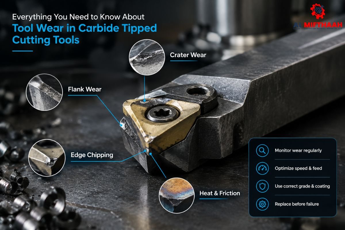
- Flank wear
A flat, shiny strip on the clearance face, just below the cutting edge, is flank wear. Abrasion causes it, and every tool develops it eventually. As the strip widens, rubbing and heat go up, the finish dulls, and part size starts to drift. A loupe shows the strip clearly, and the workpiece often looks burnished. Slightly lower speed, a harder grade for abrasive material, and coolant that reaches the edge usually help.
- Crater wear
Chips sliding across the rake face can wear a scooped-out hollow just behind the edge. That is crater wear, and heat and diffusion cause it, mostly when steel is cut at high speed. It weakens the edge, changes how chips curl, and can end in sudden breakage. Under a loupe, you will see the hollow, and the chips may change colour. Lower speed, a coated grade that insulates the carbide, and good coolant to keep the chip moving all slow it down.
- Notch wear
Notch wear is a small groove on the edge at the depth of cut line, where it meets the surface of the workpiece. Work-hardened skin, scale or a hard outer layer hits the same spot every pass, so it turns up often in stainless steels and heat-resistant alloys. The groove leaves burrs and a mark line on the part and can start a fracture. Varying the depth of cut between passes keeps one point from taking every load, and a tougher grade helps.
- Chipping
Interrupted cuts, vibration, long overhang, a grade that is too hard, or an aggressive feed can all break small pieces out of the edge. The finish gets rough, burrs appear, and dimensions jump, and the edge looks ragged under magnification. Shorten the overhang, clamp more rigidly, ease the feed on entry and exit, and consider a tougher grade.
- Edge rounding
Edge rounding slowly turns the sharp edge into a radius. It is common in abrasive materials such as high-silicon aluminium, or when the grade is too soft. Cutting force and heat rise, and burrs get larger. The edge looks dull and rounded, sometimes with a bright burnished line. Pick a grade and coating suited to the material, keep speed in range, and change the tool on time.
- Thermal cracking
Comb cracks are fine cracks running at right angles to the cutting edge. They come from repeated heating and cooling, which is common in milling and interrupted cutting, and coolant that switches on and off or reaches the edge unevenly makes them worse. They are hard to see without magnification, and they grow into chips. Use either steady flood coolant or dry cutting, and pick a grade with good thermal shock resistance.
- Built-up edge
When workpiece material welds onto the cutting edge, you get a built-up edge. It appears at low cutting speeds, with soft, sticky materials such as aluminium, low-carbon steel and some stainless steels, and with poor lubrication. It leaves torn surfaces and varying dimensions, and when it breaks off, it can take carbide with it. You will see a rough lump on the edge. Raise the speed within safe limits and use a sharp, positive geometry, a polished flute surface, and proper lubrication.
| Wear Type | What You See | Common Cause | Effect on Machining | Possible Solution |
| Flank wear | Flat strip on clearance face | Abrasion, speed too high | Dull finish, size drift | Lower speed, harder grade |
| Crater wear | Hollow on rake face | Heat, diffusion in steel | Weak edge, sudden breakage | Coated grade, better coolant |
| Notch wear | Groove at depth of cut line | Scale, work-hardened skin | Burrs, mark lines | Varying depth of cut |
| Chipping | Ragged edge | Interrupted cut, vibration | Rough finish, breakage | Rigid setup, tougher grade |
| Edge rounding | Dull, rounded edge | Abrasive material | Higher force and heat | Right grade, timely change |
| Thermal cracking | Fine cracks across edge | Heat cycling, uneven coolant | Edge chipping | Steady or no coolant |
| Built-up edge | Material stuck on edge | Low speed, sticky material | Torn finish, edge damage | Higher speed, sharp geometry |
Real-world machining scenarios
These five scenarios are illustrative, based on typical shop-floor conditions.
- Take a steel shaft turned with a brazed carbide tipped single point tool. After a handful of shafts, diameters drift, and the finish turns dull. Flank wear from a cutting speed set too high for the grade is the likely cause. Lower the speed, check it against the manufacturer’s data, and set a change interval based on measured wear.
- A shaft with a keyway shows a different problem. The tool chips each time it exits the keyway, most likely from repeated impact, a hard grade and a high feed. Reduce the feed at entry and exit, move to a tougher grade, and shorten the overhang.
- In aluminium profiling with a single flute end mill, aluminium sticks in the flute and the wall finish tears. That is built-up edge from low spindle speed and weak lubrication. Raise the speed within the machine’s limits, add suitable lubrication, and clear chips away from the cut. Single Flute Carbide Endmill UAE will be beneficial.
- Milling mild steel with a carbide end mill while the coolant switches on and off produces tiny comb cracks, followed by chipping. Steady coolant flow, or fully dry cutting, solves it.
- On a long, hot pass in alloy steel, the rake face develops a crater, chips discolour, and the edge fails without warning. Reduce speed, use a coated grade, and improve coolant delivery.
What factors influence carbide tool wear?
No single setting decides tool life, because these factors interact:
- Cutting speed: the biggest driver of temperature. Too high and wear accelerates quickly.
- Feed rate: too low causes rubbing, too high overloads the edge.
- Depth of cut: affects load and where notch wear forms.
- Workpiece material: its hardness, abrasiveness, and stickiness all change the wear pattern.
- Carbide grade: harder grades resist abrasion, tougher grades resist shock.
- Tool geometry: rake and clearance angles affect cutting force and heat.
- Coolant and lubrication: controls temperature and chip flow, but inconsistent flow can crack the edge.
- Machine rigidity and workholding: any looseness lets vibration reach the edge.
- Cutting temperature: the common thread behind crater wear, diffusion, and cracking.
- Interrupted cutting: repeated impact and thermal cycling punish brittle carbide.
Moreover, exact values depend on the workpiece, grade, coating, and machine, so start from the tool manufacturer’s recommended parameters and adjust from there.
How do you know when to replace a tool?
Waiting for a tool to fail usually costs more than changing it early. Watch for these signs:
- The surface finish gets streaky, torn, or smeared.
- Spindle load climbs, or the cut feels heavier.
- Chatter appears where the cut used to be stable.
- Parts start drifting out of tolerance.
- A loupe shows chips, a flank strip, or a crater on the edge.
- Chips, workpiece, or tool shank run hotter than before.
- The cutting note changes: squealing, rumbling, or anything unusual.
- Burrs get bigger.
When one of these appears, check the edge. Recording how many parts each tool produced before the signs showed up gives you a more reliable change interval than a calendar.
Normal wear vs premature tool failure
Normal wear is progressive and predictable. A new tool wears quickly for a short time as the edge settles, then wears slowly and steadily through most of its life, then wears fast again near the end. The wear is even along the edge, mostly flank wear, and the tool gives you plenty of warning.
Premature failure looks different:
- Chipping, fracture, or thermal cracks well before the expected number of parts.
- Uneven damage in one spot on the edge.
- Deep craters or notches that appear early.
- Sudden breakage with little or no warning.
The difference comes down to cause. Normal wear comes from the cutting itself. Premature failure is almost always a process problem, such as wrong speed, wrong grade, poor rigidity, or inconsistent coolant, and it can usually be fixed.
How can you extend carbide tool life?
- Start from the manufacturer’s cutting data and adjust gradually.
- Choose a harder grade for abrasion and a tougher one for interrupted cuts.
- Use sharp, positive edges for aluminium and stronger edges for steel.
- Give the edge steady coolant, or none at all. Switching it on and off is what causes thermal cracks.
- Clamp the workpiece firmly, because movement in the clamp shows up as vibration at the edge.
- Fix the machine’s weak points. Worn gibs, loose spindles, and flimsy fixtures all end up as tool wear.
- Keep overhang as short as the job allows, since extra stick-out invites chatter and chipping.
- Inspect edges regularly and log how long each tool lasts.
How to choose the right carbide cutting tool?
Start with the workpiece material, then work through these factors:
- Machining operation: turning, boring, profiling, slotting, and finishing each prefer different tools.
- Cutting speed and feed rate: the tool must suit the range your machine can run.
- Tool diameter: larger diameters add stiffness; smaller ones reach tight features.
- Number of flutes: fewer flutes give more chip space for aluminium; more flutes give a finer finish in steel.
- Tool coating: some coatings suit steel, others suit aluminium. Coatings containing aluminium can pick up aluminium workpiece material, so follow the manufacturer’s guidance.
- Required surface finish: tighter finishes need sharper edges and stable conditions.
- Machine capability: spindle speed, power, and rigidity set realistic limits.
When you evaluate a Carbide Tipped Single Point Tools supplier in Dubai, ask which grades suit your material and whether they can explain the geometry options. You can also talk about grades and geometry with Almifthaah before you order.
Why does tool selection matter in Dubai?
Dubai and UAE workshops run a wide mix of work, from aluminium profiles and fabricated steel to machined shafts and general maintenance jobs. Hot workshop conditions and long production runs add to the thermal load on tools, which makes consistent coolant and the right grade more important.
When specifying a carbide tip single point tool, Dubai workshops should confirm shank size, tip grade, and the material it is designed for, and ask about more than price. For aluminium work, a Single Flute Carbide Endmill UAE workshops can source locally is usually worth considering because the large chip space helps avoid built-up edge. Reliable supply matters too. A good carbide endmill supplier in Dubai should be able to deliver the same grade and geometry on the next order, so tool life stays predictable.
Almifthaah supplies precision tools and abrasives in the UAE, and many buyers know the business as a Saif Precision tools supplier in UAE. Whichever supplier you use, give them the workpiece material and the operation up front so they can recommend the right tool.
Bottom line
Some tool wear is unavoidable. Chipping, cracking, early craters, and built-up edges are different: they point to something in the setup, parameters, or tool choice that needs attention.
Read the wear on the edge, match the grade and geometry to the material, keep the cut stable and cool, and change tools when the edge, finish, and dimensions say so. A carbide tip single point tool Dubai supplier who understands these points makes that easier to do. With the right tooling and parameters, you get longer tool life, steadier production, and more consistent parts. Almifthaah, like any supplier, is best judged on the advice it gives along with what it has in stock.
Frequently asked questions
Abrasion, adhesion, diffusion at high temperature, and thermal or mechanical fatigue. Which one dominates depends on the workpiece material and cutting conditions.
There is no fixed number. Life depends on material, speed, feed, grade, and setup. Track parts produced per tool and replace based on measured wear.
Flank wear, crater wear, notch wear, chipping, edge rounding, thermal cracking, and built-up edge. Each looks different and has its own cause.
Follow the manufacturer’s parameters, match grade and geometry to the material, keep coolant steady, clamp rigidly, and keep overhang short. Inspect edges regularly.
Yes. Higher speed raises cutting temperature, which speeds up flank wear, crater wear, and diffusion. A speed that is too low can cause built-up edge in soft materials.
Replace it when the finish worsens, vibration or cutting force rises, dimensions drift, or the edge shows damage. Waiting for breakage puts the part and the machine at risk.
Usually from shock. Interrupted cuts, vibration, long overhang, a grade that is too hard, and too much feed at entry and exit are the common causes.
Steady coolant controls temperature and clears chips. If it flows intermittently or unevenly, thermal cracks can form, so let it flow consistently or not at all.
It is workpiece material welding onto the cutting edge, common in aluminium and low-carbon steel. Raise the speed, use sharp geometry and polished flutes, and lubricate properly.
No. Steady, even flank wear is normal. It becomes a problem when it grows quickly, is uneven, or starts to affect finish and size

How Long Do Mounted Points Last and When Should You Replace Them?

Everything You Need to Know About Tool Wear in Carbide Tipped Cutting Tools