

- November 21, 2026
- by Almifthaah
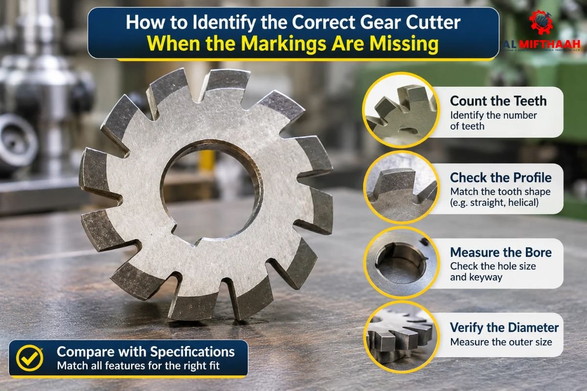
How to Identify the Correct Gear Cutter When the Markings Are Missing
An unmarked gear cutter can be a troublesome issue. There is no way of telling whether it is intended to produce gears with a 2 mm module or one with an 8 diametral pitch, whether it is made for cutting gears with a 14.5° or a 20° pressure angle, and which tooth numbers it is meant to work with. Thankfully, the process of identifying the proper cutter involves simple measurements, a few calculations, and the making of a few test cuts.
In this guide, you will learn what to do in order to measure the outside diameter and the bore, determine the module or diametrical pitch of a particular gear, check the pressure angle, find the cutter number corresponding to your findings, and make sure it matches the gear before the actual production process.
Table of Contents
ToggleKey takeaways
- Accurately measure and record outer diameters, bores, and faces of cylinders.
- Calculate a module or diametral pitch by applying the proper gear ratio calculation method.
- Verify pressure angle and cutter numbers before conducting tests and mesh verification.
- Get information from reputable milling tool suppliers to choose a cutter based on measurements.
What is a gear cutter and why does marking matter?
A gear cutter is a rotating tool that cuts the teeth of a gear from a blank. It is typically marked with the module or diametral pitch, the pressure angle, and the cutter number that describe exactly which gears it can manufacture. The cutting machine doesn’t have any obvious idea of what to do if it’s not given these details.
Gear cutting is merely one of the various cutting and milling tools Dubai workshops rely on on a regular basis. They are available in various varieties. Disc-type form cutters are also known as involute gear cutters, and are mounted on a milling machine arbor, cutting one tooth space at a time on the blank, which is indexed between cuts. End mill style gear cutters operate in the same way, but are supported by a shank. Hobs and gear shaper cutters have higher volume or more specialised applications, and both are used in a continuous or reciprocating motion. Every family is different and requires different dimensions and fittings, and the first step is always to identify the family.
Why does marking matter so much?
A cutter designed for the wrong module leaves a set of teeth with virtually the correct shape but not fitting properly. Either too thick or too thin teeth produce noise, vibration, wear, and, in extreme cases, tooth breakage. If the wrong pressure angle is used, a gear may be produced that has a lower contact ratio, which means that fewer of the teeth are in contact at any one time. Correct identification not only contributes to savings of material, machine time, and scrap; it also helps safeguard the reputation of the work produced.
Why do gear cutter markings go missing?
Unless the shop is a working one, stamped markings are seldom permanent. There are several common reasons why a cutter may arrive without a label or with numbers that can’t be read:
- As the stamp is repeatedly ground, the surface will be slowly abraded, particularly on the cutting surface.
- Engraved marks are filled with oil, coolant residue, and metal chips, making them unreadable.
- Heavy cutting or grinding may cause the surface to become discoloured and make markings difficult to see.
- Second-hand items from closed workshops and auctions may come without documentation.
Moreover, all of these situations arise regularly and continue to be a necessary part of a machinist’s skill set. It’s not about substituting the marks for guesswork. It is to be able to reproduce the specifications from the tool and from the gears that it has manufactured. If an unknown cutter is converted to a systematic approach, then this becomes a recorded cutter, and a record will be valuable for all subsequent jobs.
What measurements do you need before you start?
Collect precise information before making any calculation. Use a micrometer or digital caliper, and be sure to clean the cutter before using it to prevent any residue from impacting readings. Follow the steps below in the order given:
- Clean the cutter and check for chips, burrs, cracks, or regrinding.
- Take two or three readings around the circumference of the cutter at the cutting edge and measure the outside diameter.
- Take the bore diameter measurement because it should be exactly the same as your arbor or spindle.
- Determine the width or thickness of the face of the cutter.
- Check for a keyway and note the width.
- Take pictures of both sides of the cutter to compare it with catalogue drawings later.
Write each value on a piece of paper or in a spreadsheet. Having a set of consistent readings will make it much easier to compare with supplier catalogues, and also, if one reading appears suspicious, you can repeat the reading. Spend time on this part since all of the following calculations will rely on that one.
However, a reading that is a couple of hundredths of a millimetre off is rarely going to make any significant difference, but a faulty edge or bent bore can lead you in a totally different direction.
How do you calculate the module or diametral pitch?
The best way to find the module or diametral pitch is to use a gear that the cutter will produce, or to use a sample gear that the same cutter produced. The outside diameter of a standard full-depth involute gear is simply related to its number of teeth (N) and its module (m) by OD = m × (N + 2). When rearranged, the module is equal to the outside diameter over 2 and the number of teeth. Since the body size of the cutter does not accurately indicate the module, the module of the gear being cut is the best indicator.
Let’s take 20 teeth and an outside diameter of 66 mm and divide 66 by 22 (20+2) to get the module, 3 mm. To check this, multiply 3 by 22, which is 66 mm. If the value of your calculation is not one of the standard values or modules (2, 2.5, 3, 4, or 5 mm), repeat the measurement. A worn or chipped gear can cause the outside diameter to be distorted, and a miscounted tooth will make a significant difference.
It also assists in repeating the calculation using a second gear (if available). Two independent results that agree provide far more assurance than one result. If the two figures are different, check for wear, damage, or a counting error before proceeding.
- Checking Diametral Pitch in Inch Systems
Workshops that work in inch units utilize diametral pitch (DP) instead of module. DP = (N + 2) / OD (where OD is measured in inches). This works out to 22 ÷ 2.75 = 8 on a gear with 20 teeth and an outside diameter of 2.75 inches. The 8 diametral pitch cutter is, therefore, the right match. It is important to understand that it’s not possible to switch units such as module and diametral pitch; if you have a gear in one unit system, then the gear used in the other will not be applicable. One of the most frequent and expensive errors when working with gears is combining the two.
- Counting Teeth Accurately
Counting teeth may seem easy, but when it comes to a gear with many small teeth, mistakes are easily made. Start by marking the first tooth with a fine marker or a small piece of tape, then proceed to count around the whole circumference. Make sure to return to the same marking only once. Count the gears again before trusting the figures you have obtained. A mistake in counting even one tooth will lead to a significant change in the module as this shows that it is the most common source of incorrect selection of cutters performed in the fast-paced workshops.
How do you check the pressure angle?
The angle of pressure is defined as the angle between the line of action of a gear tooth and the tangent of the pitch circle. The majority of the latest gear cutters make use of 20°; however, older machine tools usually utilize 14.5°. This parameter can influence the shape of the gear teeth, their strength, and the ability to mesh.
If you do not have the tracking tool, you could use a gear tooth vernier to determine the chordal thickness of the tooth and compare it with the calculations obtained for both angles. An optical comparator or profile projector can deliver better precision.
Basically, a 20° tooth has better root strength and a lower risk of undercutting for small pinions, while the older design with a 14.5° tooth is usable for the usual application. Thus, ensure that the tooth root is analyzed and compared with the reference tooth before choosing the cutting tool.
Which cutter number matches your gear?
Gear cutters are mostly classified in sets that usually contain 8 cutters that include some module and pressure angle. The number designates the number of teeth. Therefore, if you know the number of teeth on the gear being machined, you can find the right cutter number in the cutter set. The classic 8 Cutter set is usually used to create 14.5-degree gears.
| Cutter Number | Tooth Range (14.5° Set) |
| No. 1 | 135 teeth to rack |
| No. 2 | 55 to 134 teeth |
| No. 3 | 35 to 54 teeth |
| No. 4 | 26 to 34 teeth |
| No. 5 | 21 to 25 teeth |
| No. 6 | 17 to 20 teeth |
| No. 7 | 14 to 16 teeth |
| No. 8 | 12 to 13 teeth |
You must take standard cutter ranges into account merely as a reference, not as a solution. 20-degree cutters have a different tooth specifications, and each manufacturer has its own chart. Always consult your manufacturer’s catalogue for your specific family of cutters. For example, while a 20-tooth cutter falls in the No. 6 category of 14.5-degree cutters, please ask the manufacturer if they use the same chart as you beforehand.
Cutter number alone is not enough; module and pressure angle should also be taken into account. A No. 6 cutter for a 2 mm module and 20 degrees is not interchangeable with a No. 6 cutter for a 3 mm module and 14.5 degrees. It is advisable to note down the cutter number in connection with its module and pressure angle.
How can a test cut confirm the right cutter?
For identification, a test cut is made from a piece of soft material, which is then compared to an existing gear in terms of the number of teeth and outside diameter, and a test mesh for the outside diameter of the teeth. If all three match, it is very likely the cutter is right. Even if measurements appear to be convincing, test cuts cost very little in comparison to a lost batch of expensive metal, so test cuts should be made for each unknown cutter.
Follow these steps for a reliable test:
- Choose a soft sample blank, such as aluminium, brass or nylon, with a bore and face width suited to your setup.
- Attach the cutter to the blank centre on the arbor and carefully position the cutter to the blank centre; set the depth of cut in small increments.
- Write an index on the blank and make 1 or 2 teeth first. Stop and check the tooth form before continuing.
- When the first teeth appear correct, put the rest of the equipment.
- Take the outside diameter of the finished sample and count the teeth on the sample.
- Use the formula from the previous section to calculate the module or diametral pitch.
- If you have a known good gear of the same module and pressure angle, try meshing it with the sample gear and verify smooth rotation, with minimal backlash.
- Examine the tooth profile visually for undercut at the root or pointed tips, which indicate a wrong cutter or setup.
Should the sample fail to pass any of these tests, do not make it for production. It is not possible to resolve a wrong-module issue by altering feed rates and depth of cut. Generally, it is preferable to go back to their measurements and rethink the cutter number and family.
Therefore, ensure that sample material is retained as a physical specimen and identify it with the identity that you came up with, so that future work with the same cutter will have a known starting point.
Which identification method is most reliable?
The most effective method is a combination of measurement, calculation, and test cut. A visual inspection is quick but can be misleading, and a test cut is the most conclusive. To get the best of both worlds, speed and accuracy, the table below shows the main methods and how to choose the right one for your workshop.
| Method | Accuracy | Typical Time | Best Use |
| Visual inspection | Low | A few minutes | Initial sorting of unmarked cutters |
| Caliper and micrometer measurement | Medium | 15 to 30 minutes | Outside diameter, bore, and face width checks |
| Module calculation from a sample gear | High | 20 to 40 minutes | Confirming module or diametral pitch |
| Pressure angle measurement | High with a profile projector | Varies | Critical or mating gear work |
| Test cut and mesh check | Very high | Depends on gear size | Final confirmation before production |
These time estimates are approximate, depending on the size of the gears and your experience with the gear. In practice, most workshops employ the first three methods to quickly sort out the cutters and then make a test cut of any cutter that is proposed to be used for important work. If the cutter passes all the checks, then it is a cutter you can trust; if the cutter fails any check, then it should be held back until the discrepancy is resolved.
What mistakes should you avoid?
The most common mistakes are using an old stamp, measuring a broken gear, making an assumption of 20 degrees, and not performing a test cut. Preventing these four errors will eliminate most of the problems with wrong cuts and save you time and gears.
Several other errors also cause trouble:
- Using a partially visible stamp: One of the digits may be mistyped, so check any partial mark against the measured value before accepting it.
- Measuring a worn or damaged sample gear: When tips are worn, the outside diameter is decreased, and the module result will be off, possibly resulting in you using the wrong cutter altogether.
- Mixing pressure angles: If you use a 14.5-degree cutter on a 20-degree mating gear, you will get a poor result, noise, and wear.
- A lack of awareness of the metric system: A diametral pitch gear cut with a module cutter will result in teeth that will not fit together with standard gears.
- Avoiding a test cut to save time: A batch of ruined blanks and the labour to do the work is so much more expensive than a little sample.
- Buying from sellers who cannot provide references: A supplier that refuses to provide a supplier catalogue number and technical information is easier to let off the hook if the tool is found to be incorrect.
Furthermore, all of these errors are things that can be easily avoided by having a simple list. Record your measurements, compare them to catalogue data, and never go to production without test pieces.
How do you choose a trusted supplier in Dubai?
The best supplier is one that stocks standard cutter families, provides catalogue references, can help match an unmarked cutter, and offers clear return or exchange terms. Local suppliers are particularly helpful if you need to replace parts quickly, or if you need tips that are based on workshop conditions in your area. Take the sample equipment and data to the discussion for the best match.
When looking for gear cutters suppliers in Dubai, don’t only consider the price. A reliable dealer can explain the differences between cutter families, confirm the module and pressure angle for a given cutter, and suggest a suitable cutter number for your gear. Many workshops are better off dealing with gear cutters Dubai that know the bigger picture of the machining processes, the arbor sizes, the compatibility of various machines, and the materials your work team uses most frequently.
What to ask before you buy?
The following short list of questions will quickly show you how knowledgeable a supplier is. Before you order, you should think about the following:
- Which module or diametral pitch and pressure angle is the cutter made for?
- Can your gear cutters dealers in Dubai beat an unmarked cutter with your sample gear?
- What catalogue or datasheet number does the specific brand of cutters you are purchasing correspond to?
- What the return, exchange, and regrinding policies are, and how long they take?
- Check if the bore and keyway fit the arbor or spindle when not modified.
The suppliers who can clearly answer these questions in writing will be easier to deal with later, particularly if there is a problem that is only noticed after delivery.
Why do local stock and support matter?
Partnering with a supplier who is located close by minimizes downtime. If a cutter breaks or if there is a sudden shift in the job, a local dealer can handle the replacement much quicker than importing from a faraway supplier. The dealer’s expertise will help you with various aspects of tool maintenance, such as how to store them as well as how to sharpen a tool once it’s worn out.
So if you compare best milling tools dealers UAE prices, keep in mind that technical assistance is equally important as the price. An experienced local supplier can advise on the right tools for local materials and practices, thus saving a lot of money.
Conclusion
Identifying the right gear cutter without any markings requires a careful and structured process of measuring, calculation, and verification. Confirming gives us straight measurements of outside diameter, bore, and face width. Then, using a sample gear allows us to find the module or diametrical pitch, verify the pressure angle, find the cutter number, and perform a test cut to affirm the data before commencing the manufacturing process. All of this takes an insignificant amount of time but helps a lot in preventing costly errors associated with speculating.
If you are looking for a trustworthy supplier of gear cutters, consider suppliers based in Dubai that can use your specifications and offer clear technical references. Almifthaah is a known supplier of Saif Precision tools supplier in UAE, so you could visit almifthaah.com and check their currently available products. Be sure to keep records of your measurements and tag your samples so that you will create a good reference library for future purposes.
Frequently asked questions
Not reliably. Visual clues help to narrow down choices, while an accurate identification requires a micrometer, calipers, and a sample gear for measurement purposes.
Check the diameter and tooth count beforehand. In case of failure to match the numbers, then the gear may be profile-shifted or non-standard.
Find a dealer who provides catalogue information, technical support services, and good return policies. Request sample sizes for big order requests.
Usually yes. A similar-looking cutter may have different modules or angles of attack; testing it is an inexpensive way to verify its compatibility

How to Identify the Correct Gear Cutter When the Markings Are Missing

Carbide Tool Maintenance Tips Every Machinist Should Know